
Thermal Lens
Before you begin
You should know steady conduction, integration and the small-angle approximation. The optical-path principle needed for the focusing argument is stated below.
A laser heats the centre of a flat disc. The resulting temperature variation changes the refractive index, so the transmitted beam can focus even when the disc faces remain flat. We will first find the temperature profile, then compare optical paths to locate the focus.
The problem
A thin semitransparent disc is held at its circular rim by a metal holder. A parallel laser beam falls normally on the centre. Its incident intensity is uniform inside beam radius \(s\) and zero outside. A fraction \(\alpha\) of the incident power becomes heat in the disc.
| Quantity | Value |
|---|---|
| Disc radius \(a\) | \(15.0\,\mathrm{mm}\) |
| Disc thickness \(b\) | \(0.20\,\mathrm{mm}\) |
| Conductivity \(k\) | \(0.30\,\mathrm{W\,m^{-1}\,K^{-1}}\) |
| Rim temperature \(T_{\mathrm{h}}\) | \(20\,{}^\circ\mathrm{C}\) |
| Beam radius \(s\) | \(0.50\,\mathrm{mm}\) |
| Incident power \(P_L\) | \(20\,\mathrm{mW}\) |
| Absorbed fraction \(\alpha\) | \(0.10\) |
| Index coefficient \(\gamma=\mathrm{d}n/\mathrm{d}T\) | \(2.5\times10^{-4}\,\mathrm{K^{-1}}\) |
Assume steady radial heat flow, uniform temperature through the thickness and constant material properties. Neglect thermal expansion, thermal radiation and heat exchange with air. The rim remains at \(T_{\mathrm{h}}\). For transmitted light, take \(n_{\mathrm{air}}=1\) and use the thin-element, small-angle approximation.
Part a — 2 marks. Sketch the temperature \(T(r)\), where \(r\) is distance from the beam axis. Distinguish the illuminated spot, \(0\leq r\leq s\), from the outer annulus, \(s\leq r\leq a\).
Part b — 4 marks. Near the centre, write \(T(r)=T_{\mathrm{c}}+mr^2\). Calculate \(T_{\mathrm{c}}\) and \(m\).
Part c — 4 marks. Show that the transmitted beam has a common paraxial focus and calculate its distance \(f\) from the disc. If needed, first express the result in terms of \(m\).
Optical principle. Optical path length is refractive index times geometrical distance, summed over the media. Rays from the same incident plane wavefront that meet at a focus have equal optical paths within the stated approximation.
Solve the radial conduction problem
Count the heat generated inside each radius
The absorbed power is
At steady state, the heat current through a cylindrical boundary equals the power generated inside it. The uniform beam makes that enclosed power proportional to area within the spot:
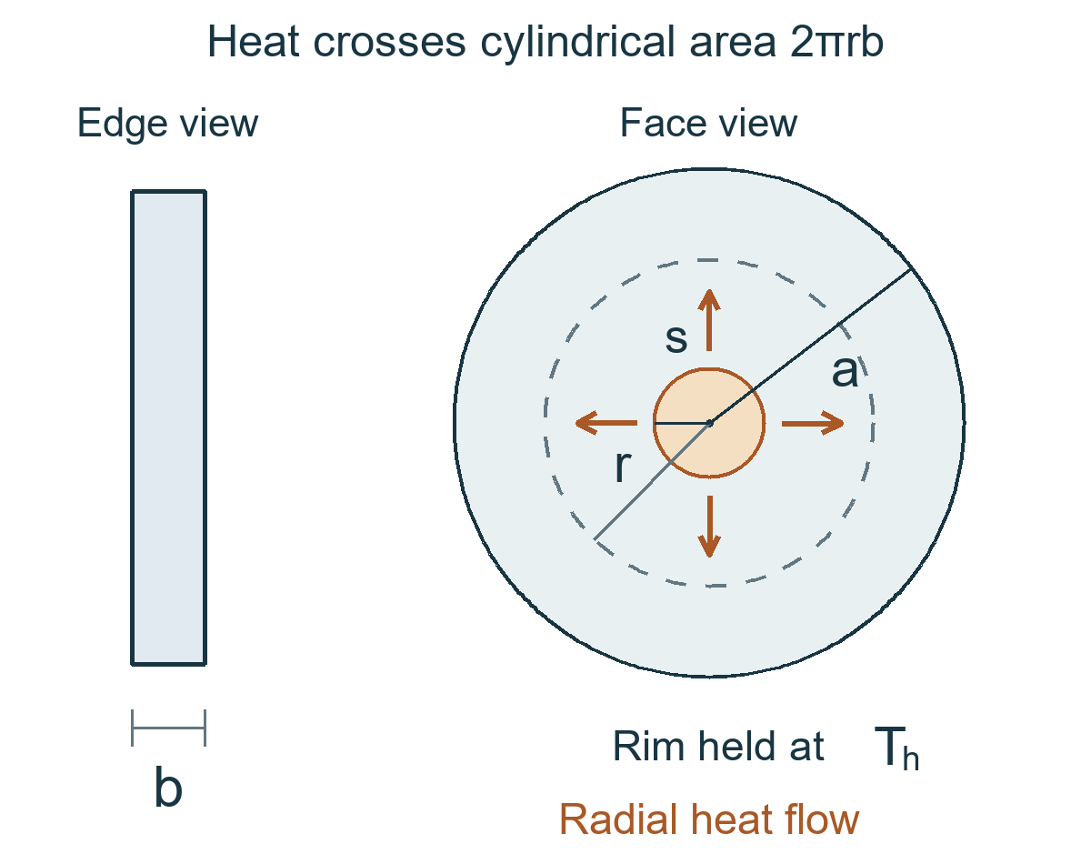
The conduction area is the cylindrical surface \(2\pi rb\). Heat moves outward toward the rim, so the relevant area is not the flat face area \(\pi r^2\). Fourier’s law gives
Integrate in the unilluminated annulus
The same power crosses every radius outside the spot:
Integrating from the fixed-temperature rim gives
Integrate inside the illuminated spot
Here the heat current decreases toward the centre because less heated material lies inside each smaller radius. For positive \(r\),
Therefore,
The central temperature is finite and the central slope is zero. Extending the outer logarithmic expression to the centre would incorrectly concentrate all the heat at a point source.
Parts a and b The temperature profile
Temperature is continuous at the spot edge. Matching the two expressions at \(r=s\) gives
Hence
In SI units, the radius ratio is \(a/s=30\) and the temperature scale is \(P_{\mathrm{a}}/(4\pi kb)=2.65258\,\mathrm{K}\). The central temperature rise is
Adding this rise to the rim temperature gives \(T_{\mathrm{c}}=40.6965\,{}^\circ\mathrm{C}\), or approximately \(41\,{}^\circ\mathrm{C}\).
The quadratic coefficient is
At the spot edge, \(T(s)=38.0439\,{}^\circ\mathrm{C}\). The temperature falls by only \(2.65258\,\mathrm{K}\) within the spot; the remaining \(18.0439\,\mathrm{K}\) drop occurs between the spot and the rim.
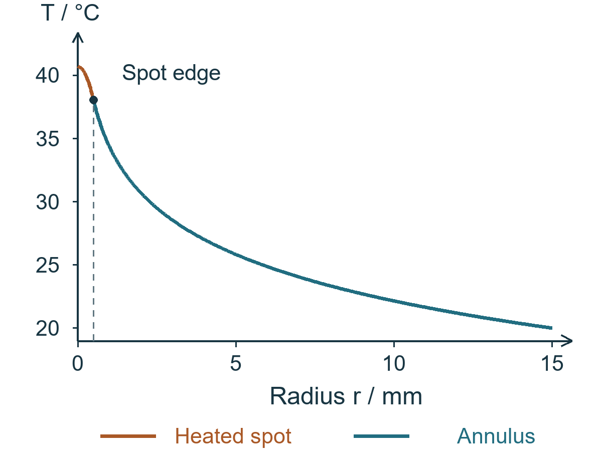
The enlarged view shows how the two regions join at the spot edge.
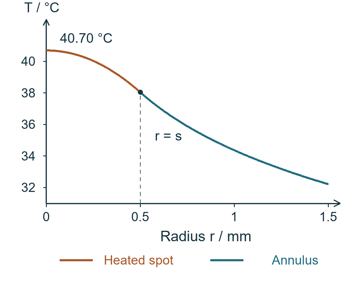
What the sketch must show
At the centre, the curve has a horizontal tangent and its highest temperature.
Inside the spot it decreases as a concave-down parabola.
Outside the spot it decreases as a concave-up logarithmic curve.
At the rim it reaches \(20\,{}^\circ\mathrm{C}\) with a nonzero negative slope: heat is still leaving the disc.
There is no sharp corner at the spot edge. Both expressions give the slope \(T'(s)=-P_{\mathrm{a}}/(2\pi kbs)\). The second derivative changes because heat is generated inside the spot but not in the outer annulus.
Part c How the flat disc focuses light
Convert temperature into refractive index
The constant coefficient \(\gamma\) gives, within the illuminated spot,
where \(n_{\mathrm{c}}=n(0)\). Since \(m<0\) and \(\gamma>0\), the refractive index is largest at the centre. Light close to the axis acquires a greater optical delay inside the disc.
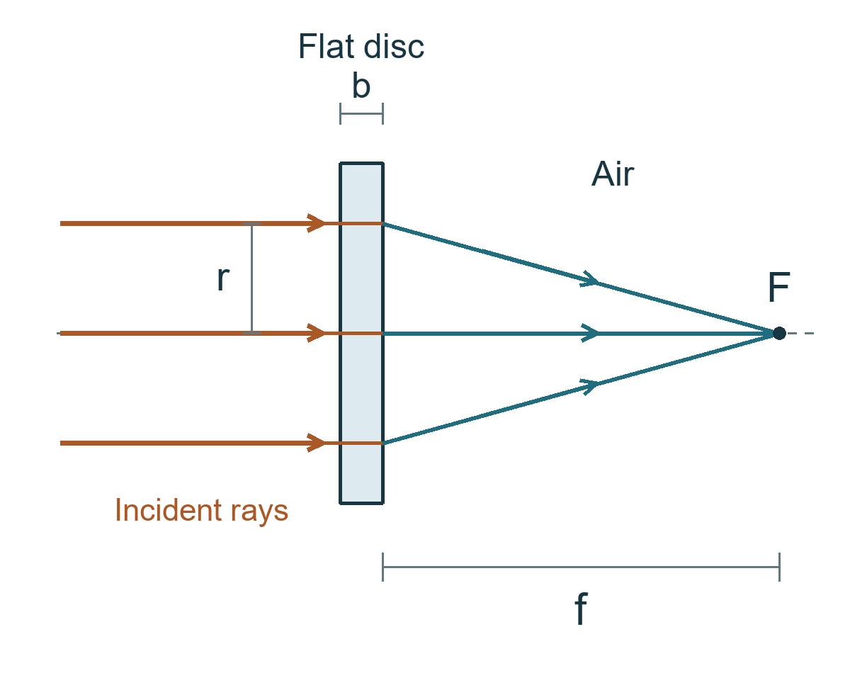
Equal optical paths give a common focus
Take the front face as a common input plane. A candidate axial focus lies a distance \(f\) beyond the rear face. In the thin-element approximation, a ray at radius \(r\) has optical path
The axial path is \(\mathcal{L}(0)=bn_{\mathrm{c}}+f\). Subtracting it gives
All illuminated rays have the same optical path when the coefficient of \(r^2\) vanishes. This gives
The result is independent of ray height, so the transmitted beam has one common focus to this order. Numerically,
The positive value gives a real focus behind the disc. Off-axis rays travel farther through air, compensating for their smaller optical delay inside the disc. Thermal expansion and curved faces are unnecessary in this model.
Checks and teaching notes
Check the small angle approximation
The largest outgoing angle is about \(s/f\). The thickness is also very small compared with the focal distance:
These small ratios support the paraxial construction and the negligible change of ray height within the disc. We do not need to assume that the thickness is much smaller than the beam radius: the given values actually give \(b/s=0.40\).
An independent check comes from the optical-path slope. In air, the small signed outward angle is approximately
For a ray above the axis, the negative sign means deflection toward the axis. Its magnitude is proportional to ray height, again giving the same focal distance for every illuminated ray. The thickness factor is necessary to make the angle dimensionless.
Why some quantities cancel
The absolute refractive index is not needed. The constant optical path \(bn_{\mathrm{c}}\) is the same for all rays and cancels in their path difference. Focusing depends on the radial variation of the index.
The rim radius changes the central temperature but not this focal length. Changing \(a\) adds a common temperature offset throughout the spot. It leaves the curvature \(m\) unchanged when other parameters stay fixed.
Thickness cancels at fixed absorbed fraction. A thinner disc has a larger temperature curvature, proportional to \(1/b\), but the light crosses a shorter optical path. The product \(bm\) remains unchanged. This comparison requires \(\alpha\) to stay fixed.
| Change with other parameters fixed | Central temperature rise | Focal length |
|---|---|---|
| Double incident power \(P_L\) | Doubles | Halves |
| Double conductivity \(k\) | Halves | Doubles |
| Double thickness \(b\), keeping \(\alpha\) fixed | Halves | Unchanged |
| Double rim radius \(a\) | Increases by \(3.68\,\mathrm{K}\) | Unchanged |
| Double beam radius \(s\) | Decreases by \(3.68\,\mathrm{K}\) | Becomes four times as large |
The common focus applies to the illuminated rays, \(r\leq s\), within the paraxial approximation. The unilluminated annulus has a different index profile and would not give a wider probe beam the same focus.