
Counterflow Heat Exchanger
Before you begin
You should know conduction through a slab, heat capacity and steady energy balance. The main solution uses algebra. A short differential argument then explains why the local temperature gap is constant.
Two fluids flow in opposite directions on either side of a conducting wall. Can the originally cold stream leave hotter than the originally hot stream? We will find both outlet temperatures and show why heat still flows from the locally warmer fluid to the locally cooler one.
The problem
Two rectangular fluid channels, each of length \(\ell\), width \(w\) and height \(h\), share a metal partition of thickness \(d\) and thermal conductivity \(\kappa\). The upper channel carries the originally cold fluid from left to right. The lower channel carries the originally hot fluid from right to left. Both streams have speed \(v\) and the same heat capacity per unit volume, \(c\).
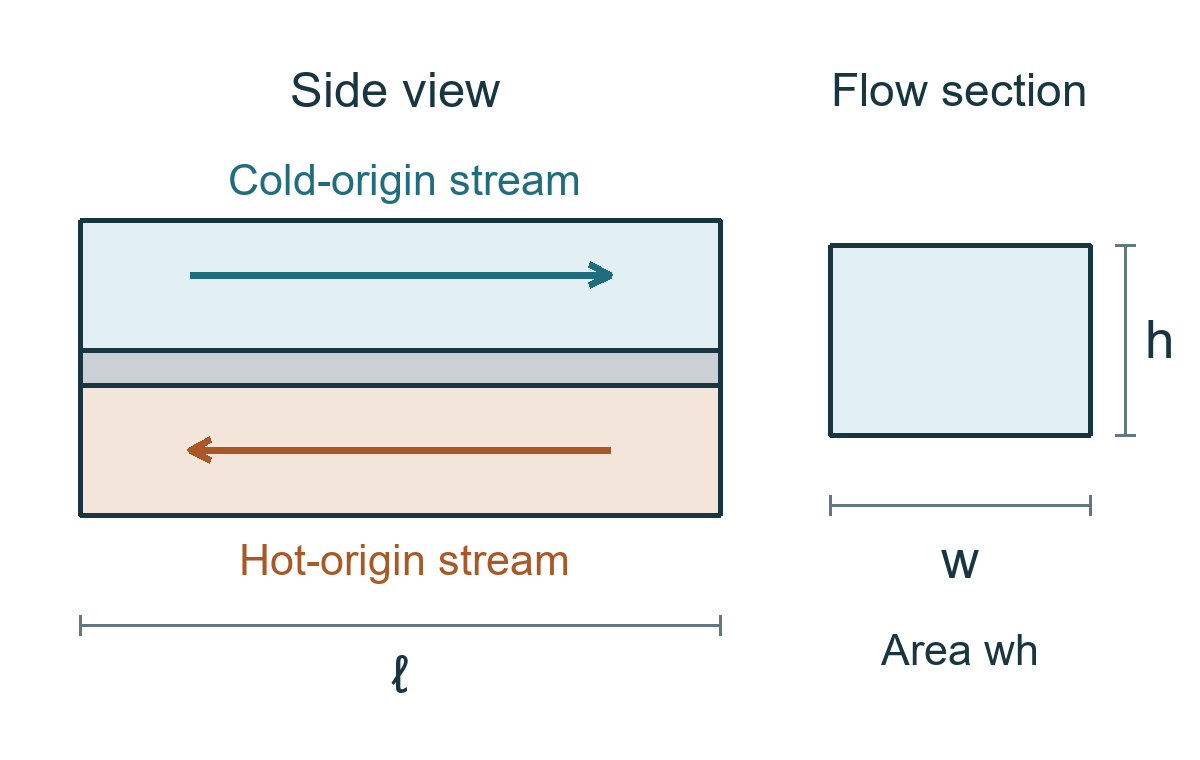
| Symbol | Meaning | SI unit |
|---|---|---|
| \(\ell,w,h\) | Channel length, width and height | \(\mathrm{m}\) |
| \(d\) | Partition thickness | \(\mathrm{m}\) |
| \(\kappa\) | Partition thermal conductivity | \(\mathrm{W\,m^{-1}\,K^{-1}}\) |
| \(v\) | Speed of either stream | \(\mathrm{m\,s^{-1}}\) |
| \(c\) | Heat capacity per unit volume | \(\mathrm{J\,m^{-3}\,K^{-1}}\) |
Use steady flow with fixed inlet temperatures and constant material properties. Each stream has a uniform temperature across its cross section, but its temperature varies along the channel. The fluids do not mix. Heat is transferred across the partition and carried along by the moving fluids. Neglect external heat losses, axial conduction and temperature drops between each fluid and its adjacent wall face.
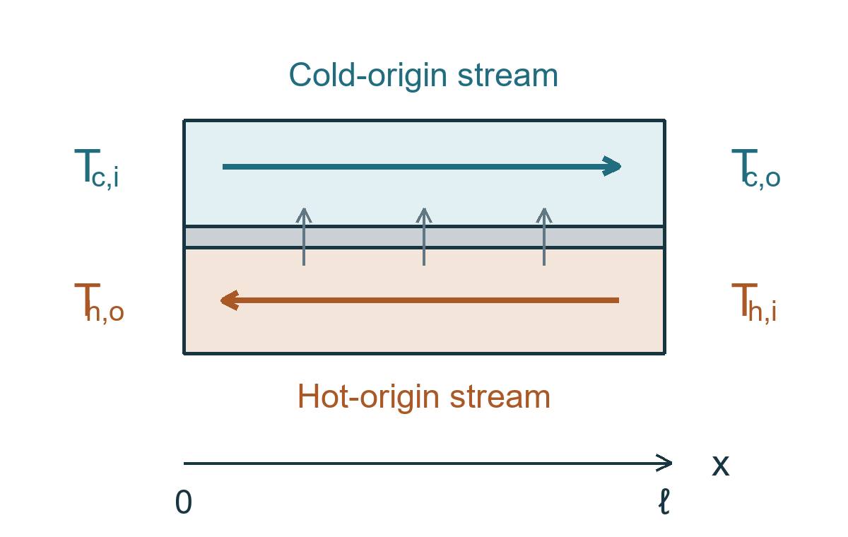
Let the subscripts \(\mathrm{h}\) and \(\mathrm{c}\) identify the originally hot and cold streams, and \(\mathrm{i}\) and \(\mathrm{o}\) identify inlet and outlet. The inlet temperature difference is
The original question permits you to use the result that the temperature difference across the partition at the same position is constant along its length.
Find the signed outlet difference \(\Delta T_{f}=T_{\mathrm{h,o}}-T_{\mathrm{c,o}}\) in terms of the given parameters. It may be negative. For a slab, the conduction rate is \(P=\kappa A\Delta T/d\).
Solution from the overall energy balance
Keep the three temperature differences separate
Take \(x=0\) at the left end and \(x=\ell\) at the right end. Define the local wall gap as \(\Delta T_{w}=T_{\mathrm{h}}(x)-T_{\mathrm{c}}(x)\). This compares adjacent fluids, whereas \(\Delta T_{i}\) and \(\Delta T_{f}\) compare temperatures at opposite ends.
Convert conduction and fluid flow into heat rates
The partition conductance \(G\) and the heat-capacity rate \(\dot{C}\) of either stream are
Both \(G\) and \(\dot{C}\) have units \(\mathrm{W}\,\mathrm{K}^{-1}\), so \(N\) is dimensionless. To obtain \(\dot{C}\), note that a volume \(vwh\, dt\) passes in time \(dt\); its heat capacity is \(cvwh\, dt\). No density factor is required because \(c\) is already a volumetric heat capacity.
The total conducted power is \(P=G\Delta T_{w}\). At the left end, \(T_{\mathrm{h,o}}=T_{\mathrm{c,i}}+\Delta T_{w}\). The hot stream therefore cools by \(\Delta T_{i}-\Delta T_{w}\), giving
Compare the outlet temperatures
At the right end, \(T_{\mathrm{c,o}}=T_{\mathrm{h,i}}-\Delta T_{w}\). Consequently,
This is the requested answer. The outlet order reverses when \(N>1\), or \(\kappa\ell >dvhc\). For every finite \(N>0\), the local wall gap remains positive and conduction transfers heat from the locally warmer stream to the locally cooler stream.
Why the local temperature gap is constant
This proof explains the result supplied in the question. The essential symmetry is that the two streams have equal heat-capacity rates and flow in opposite directions.
Balance a short section of each channel
For a section between \(x\) and \(x+dx\), write \(\delta(x)=T_{\mathrm{h}}(x)-T_{\mathrm{c}}(x)\). The heat-transfer rate across that small wall area is
The cold stream enters this section at \(x\) and leaves at \(x+dx\). The hot stream enters at \(x+dx\) and leaves at \(x\). Its inlet-to-outlet temperature drop therefore has the same algebraic order as the cold stream’s temperature rise:
Divide by \(dx\) and take the limit. The spatial derivatives are equal:
Thus \(\delta(x)=\Delta T_{w}\) is constant. Equal spatial slopes do not mean both fluids warm as they move: the hot stream travels towards decreasing \(x\) and cools along its actual direction of motion.
Obtain the complete temperature profiles
The common slope is \(N\Delta T_{w}/\ell\). Using \(T_{\mathrm{c}}(0)=T_{\mathrm{c,i}}\) gives
At \(x=\ell\), the second equation gives \(T_{\mathrm{h,i}}=T_{\mathrm{c,i}}+\left( 1+N \right)\Delta T_{w}\), reproducing the earlier result. The two profiles are parallel and never cross at a common position.
A useful alternative form for the heat rate
The inlet gap is the sum of the local wall gap and either stream’s total temperature change:
This resembles a series-resistance formula. Here \(1/\dot{C}\) describes the temperature change of a flowing stream per unit heat rate; it is not an additional solid wall.
Numerical illustration and temperature profiles
The following values are chosen only to check and illustrate the symbolic solution; they are not additional data from the competition paper.
| Parameter | Illustrative value |
|---|---|
| Length \(\ell\) | \(1.00\,\mathrm{m}\) |
| Width \(w\) | \(0.200\,\mathrm{m}\) |
| Channel height \(h\) | \(0.0100\,\mathrm{m}\) |
| Wall thickness \(d\) | \(0.00500\,\mathrm{m}\) |
| Conductivity \(\kappa\) | \(15.0\,\mathrm{W\,m^{-1}\,K^{-1}}\) |
| Speed \(v\) | \(0.0500\,\mathrm{m\,s^{-1}}\) |
| Volumetric heat capacity \(c\) | \(4.00\times10^6\,\mathrm{J\,m^{-3}\,K^{-1}}\) |
| Hot inlet \(T_{\mathrm{h,i}}\) | \(80.0\,{}^\circ\mathrm{C}\) |
| Cold inlet \(T_{\mathrm{c,i}}\) | \(20.0\,{}^\circ\mathrm{C}\) |
The conductance and heat-capacity rate are \(G=600\ \mathrm{W}\,\mathrm{K}^{-1}\) and \(\dot{C}=400\ \mathrm{W}\,\mathrm{K}^{-1}\). Thus \(N=1.50\) and \(\Delta T_{i}=60.0\ \mathrm{K}\):
Each stream changes temperature by \(P/\dot{C}=36.0\ \mathrm{K}\). The outlets are therefore
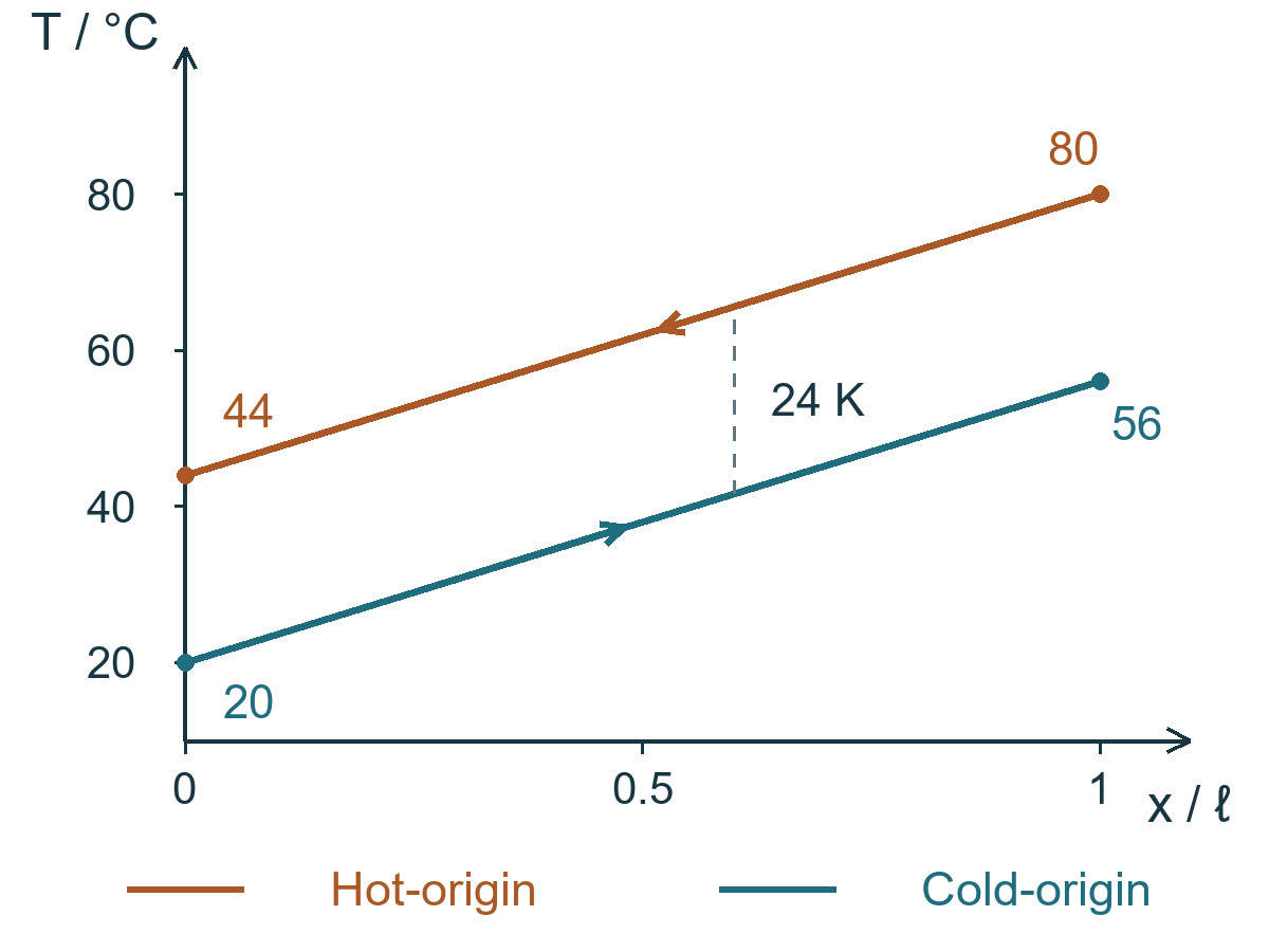
Check both streams. The hot stream releases \((400\,\mathrm{W\,K^{-1}})(80-44)\,\mathrm{K}\), or \(14\,400\,\mathrm{W}\), while the cold stream receives \((400\,\mathrm{W\,K^{-1}})(56-20)\,\mathrm{K}\), or \(14\,400\,\mathrm{W}\). The wall gives the same power: \(G\Delta T_w=(600\,\mathrm{W\,K^{-1}})(24.0\,\mathrm{K})\), also \(14\,400\,\mathrm{W}\).
Check a local pair. At \(x=\ell /2\), the stream temperatures are \(62.0\ {}^\circ\mathrm{C}\) and \(38.0\ {}^\circ\mathrm{C}\). Heat flows from the first to the second. Comparing the two remote outlets does not determine the direction of heat flow through a particular wall element.
Limits and parameter effects
The parameter \(N=G/\dot{C}\) compares the partition’s ability to conduct heat with the rate at which the streams carry heat capacity through the exchanger.
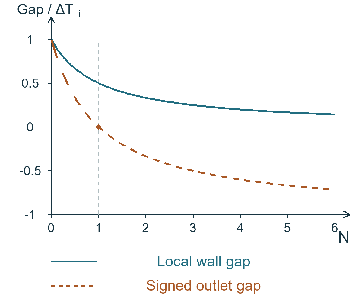
| Regime | Local gap \(\Delta T_w\) | Outlet gap \(\Delta T_f\) | Meaning |
|---|---|---|---|
| \(N\to0\) | \(\Delta T_i\) | \(\Delta T_i\) | Negligible change in each stream. |
| \(N=1\) | \(\Delta T_i/2\) | \(0\) | Both outlets reach the mean inlet temperature. |
| \(N\to\infty\) | \(0\) | \(-\Delta T_i\) | Each outlet approaches the other stream’s inlet temperature. |
The limits refer to the ideal mathematical model. Complete temperature interchange is approached asymptotically, not attained at a finite positive \(N\).
How the parameters affect the result
At fixed flow and heat capacity, increasing \(\kappa\) or \(\ell\), or reducing \(d\), increases \(N\) and increases the temperature change of each stream. The fraction of the maximum possible temperature change achieved is
The width \(w\) cancels from \(N\) because both the exchange area and the volume flow rate grow in proportion to \(w\). Increasing width leaves the outlet temperatures unchanged while increasing total heat transfer in proportion to width.
Slower flow gives each stream a larger temperature change, but it also reduces \(\dot{C}\). At fixed \(G\) and inlet temperatures, \(P=G\dot{C}\Delta T_{i}/\left( G+\dot{C} \right)\) decreases when the flow is reduced. A larger temperature change per unit volume does not necessarily mean more heat transferred per second.
Sources and further reading
The symbolic problem is from the AAPT USAPhO 2013 Semifinal, Part A, Question A1. See the official question paper, page 3, and the official solution, pages 3 to 4.
The problem is restated in fresh wording. The profile derivation and numerical illustration explain the symbolic result; the example values are not additional competition data. The four scientific figures are independently prepared.